Solved Problem on Static Equilibrium
advertisement
A homogeneous rod AOB with a constant cross-section and weight 15 N is folded, making a right
angle in O, AO = 1 m and BO = 0.5 m. The bar is suspended by the point O.
Determine:
a) The angle α between segment AO and the vertical in the position of equilibrium;
b) The magnitude of the horizontal force that should be applied in point A, in the AOB plane, so that AO and BO have the same inclination relative to the horizontal;
c) In the case of item (b), find the magnitude of the reaction force at the point of suspension O.

Problem data:
- Weight of the bar: W=15 N;
- Length of the segment AO: DA=1 m;
- Length of the segment BO: DB=0,5 m.
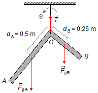
We choose point O, where the object is fixed, as a reference point. As the bar is homogeneous and
with a constant section its mass is also distributed throughout its extension, so we can consider that
the center of mass of each of the "arms" is its center. In AO the center is in
\( d_{A}=\frac{D_{A}}{2}=\frac{1}{2}=0,5\;\text{m} \),
where the gravitational force
\( {\vec F}_{gA} \)
is applied. In BO the center is in
\( d_{B}=\frac{D_{B}}{2}=\frac{0,5}{2}=0,25\;\text{m} \),
where gravitational force
\( {\vec F}_{gB} \)
is applied. At point O we have the tension force
\( \vec{T} \)
(Figure 1).
The object can rotate around the point O, we will assume the counterclockwise as the positive direction.
As the bar is bent in a 2:1 ratio, that is, an "arm" is double the length of the other (1 m and 0.5 m), and as the bar is homogeneous, its weight is distributed in the same proportion. Thus of the total of WA=FgA=10 N and WB=FgB=5 N.
Solution
a) The torque of a force is given by
\[
\begin{gather}
\bbox[#99CCFF,10px]
{{\Large \tau}=Fd} \tag{I}
\end{gather}
\]
"Forgetting" the BO segment of the object and considering only the segment AO, the
gravitational force
\( {\vec F}_{gA} \)
can be decomposed into two components, a component parallel to the "arm"
\( {\vec F}_{gAP} \)
and another component perpendicular or normal
\( {\vec F}_{gAN} \).
The angle between the segment AO and the vertical line passing through O is equal to the α, the gravitational force \( {\vec F}_{gA} \) is parallel to the vertical through O and component \( {\vec F}_{gAP} \) is in the same direction as the segment AO, then the angle between the gravitational force and the parallel component is α, are corresponding angles (Figure 2).
Only the normal component contributes to the "arm" rotate around the point O, as this component rotates in the same direction of the chosen referential, the torque of this force will be positive, applying the expression (I)
\[
\begin{gather}
{\Large \tau}_{F_{gAN}}=F_{gAN}d_{A} \tag{II}
\end{gather}
\]
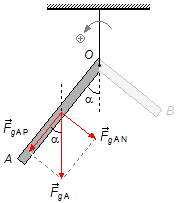
The normal component is given by (Figure 2)
\[
\begin{gather}
F_{gAN}=F_{gA}\sin \alpha \tag{III}
\end{gather}
\]
substituting the expression (III) into expression (II)
\[
\begin{gather}
{\Large \tau}_{F_{gAN}}=F_{gA}\sin \alpha d_{A} \tag{IV}
\end{gather}
\]
"Forgetting" the segment AO of the object and considering only the segment BO, the
gravitational force
\( {\vec F}_{gB} \)
can be decomposed into two components, a component parallel to the "arm"
\( {\vec F}_{gBP} \)
and another component perpendicular or normal
\( {\vec F}_{gBN} \).
The angle between the segment BO and the vertical line passing through O we label it β, the gravitational force \( {\vec F}_{gB} \) is parallel to the vertical through O and component \( {\vec F}_{gBP} \) is in the same direction as the segment BO, then the angle between the gravitational force and the parallel component is β, are corresponding angles (Figure 3). As the bar was folded at a right angle (90°) in O the sum of α and β should be equal to 90°, they are complementary angles, then β should be \( \alpha +\beta =90°\Rightarrow \beta=90°-\alpha \).
Only the normal component contributes to the "arm" turn around the point O, as this component rotates in the opposite direction of the referential, the torque of this force will be negative, applying the expression (I)
\[
\begin{gather}
{\Large \tau}_{F_{gBN}}=-F_{gBN}d_{B} \tag{V}
\end{gather}
\]
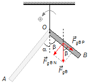
The normal component is given by (Figure 3)
\[
\begin{gather}
F_{gBN}=F_{gBA}\sin \beta\\[5pt]
F_{gBN}=F_{gB}\sin (90°-\alpha)
\end{gather}
\]
From the Trigonometry
\( \sin (a-b)=\operatorname{sen}a\,\cos b-\sin b\,\cos a \)
\[ \sin (a-b)=\operatorname{sen}a\,\cos b-\sin b\,\cos a \]
\[
\begin{gather}
F_{gBN}=F_{gB}(\sin 90°\cos \alpha -\sin \alpha \cos 90°)\\[5pt]
F_{gBN}=F_{gB}(1\times\cos \alpha -\sin \alpha \times0)\\[5pt]
F_{gBN}=F_{gB}\cos \alpha \tag{VI}
\end{gather}
\]
substituting the expression (VI) into expression (V)
\[
\begin{gather}
{\Large \tau}_{F_{gBN}}=-F_{gB}\cos \alpha d_{B} \tag{VII}
\end{gather}
\]
At point O, we have the tension force, applying expression (I)
\[
\begin{gather}
{\Large \tau}_{T}=Td_{T}
\end{gather}
\]
As the distance is zero, relative to the origin,
\( d_{T}=0 \),
the force is applied at the origin
\[
\begin{gather}
{\Large \tau}_{T}=T\times 0\\[5pt]
{\Large \tau}_{T}=0 \tag{VIII}
\end{gather}
\]
Using the condition that the sum of the torques is zero
\[
\begin{gather}
\bbox[#99CCFF,10px]
{\sum {\Large \tau}=0} \tag{IX}
\end{gather}
\]
substituting expressions (IV), (VII), and (VIII) into the condition (IX)
\[
\begin{gather}
{\Large \tau}_{F_{gAN}}+{\Large \tau}_{F_{gBN}}+{\Large \tau}_{T}=0\\[5pt]
F_{gA}\sin \alpha d_{A}-F_{gB}\cos \alpha d_{B}+0=0\\[5pt]
F_{gA}\sin \alpha d_{A}=F_{gB}\cos \alpha d_{B}\\[5pt]
\frac{\sin \alpha }{\cos \alpha}=\frac{F_{gB}d_{B}}{F_{gA}d_{A}}
\end{gather}
\]
From the Trigonometry
\( \tan \alpha =\frac{\sin \alpha }{\cos \alpha } \)
substituting the problem data
\[
\begin{gather}
\tan \alpha =\frac{5\times 0.25}{10\times 0.5}\\[5pt]
\tan \alpha =\frac{1.25}{5}\\[5pt]
\tan \alpha =0.25\\[5pt]
\alpha =\arctan \,0.25
\end{gather}
\]
\[
\begin{gather}
\bbox[#FFCCCC,10px]
{\alpha \simeq 14°}
\end{gather}
\]
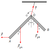
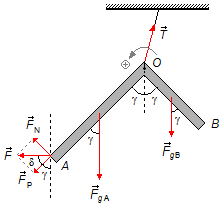
b) A force
\( \vec{F} \)
is applied at point A makes the object rotate around point O until the angles between the
two segments are equal to γ, the object is also drawn to the left so that the ceiling rope is no
more in a vertical position (Figure 4).
Note: In the condition of the item (a) the angle α between the segment AO
and the vertical was determined as 14°, therefore the angle between the segment BO and vertical
is
\( 90°-14°=76° \).
So that the two angles are equal, the object should rotate, the 14° angle increases and the 76° angle
diminishes (until 45°), this happen when the piece rotates clockwise, not to be confused with the
arrow of Figure 4 which indicates only the positive direction of the reference.
Considering only the segment, the
\( \vec{F} \)
force can be decomposed into two components, a component parallel to the "arm"
\( {\vec{F}}_{P} \)
and another perpendicular or normal component
\( {\vec{F}}_{N} \).
The angle between the segment A and the vertical per o is γ, the angle between the vertical passing by point A and the parallel component to the AO is also γ, are corresponding angles. As the force applied is horizontal it forms an δ angle with the parallel component, the sum of γ and δ should be 90° (are complementary angles), we have \( \gamma +\delta =90°\Rightarrow \delta =90°-\gamma \) (Figure 5).
Only the normal component contributes to the "arm" turn around the point O, as this component rotates in the opposite direction of the guidance chosen the moment of this force will be negative, by expression (I), where the distance from the reference point to the point of force is the length of the segment at the given
\[
\begin{gather}
{\Large \tau}_{F_{N}}=-F_{N}D_{A} \tag{X}
\end{gather}
\]
The normal component will be given by (Figure 5)
\[
\begin{gather}
F_{N}=F\sin \delta\\[5pt]
F_{N}=F\sin (90°-\gamma)
\end{gather}
\]
Using difference formula for sine shown above
\[
\begin{gather}
F_{N}=F(\sin 90°\cos \gamma -\sin \gamma \cos 90°)\\[5pt]
F_{N}=F(1.\cos \gamma -\sin \gamma .0)\\[5pt]
F_{N}=F\cos \gamma \tag{XI}
\end{gather}
\]
substituting the expression (XI) into expression (X)
\[
\begin{gather}
{\Large \tau}_{F_{N}}=-F\cos \gamma D_{A} \tag{XII}
\end{gather}
\]
For the other forces involved in the system, the above expressions are valid with the change in the angle
α in (IV) and (VII) by the new γ angle. Substituting (IV), (VII), (VIII), and (XII) into the
condition (IX)
\[
\begin{gather}
{\Large \tau}_{F_{gAN}}+{\Large \tau}_{F_{gBN}}+{\Large \tau}_{T}+{\Large \tau}_{F_{N}}=0\\[5pt]
F_{gA}\sin \gamma d_{A}-F_{gB}\cos \gamma d_{B}+0-F\cos \gamma D_{A}=0\\[5pt]
F_{gA}\sin \gamma d_{A}=F_{gB}\cos \gamma d_{B}+F\cos \gamma D_{A}
\end{gather}
\]
factoring cos γ on the right-hand side of the equation
\[
\begin{gather}
F_{gA}\sin \gamma d_{A}=\cos \gamma (F_{gB}d_{B}+FD_{A})
\end{gather}
\]
the bar is folded making a 90° angle, and we want both sides have the same inclination
\( \gamma =45° \)
From the Trigonometry
\( \cos 45°=\sin 45°=\frac{\sqrt{2\,}}{2} \)
\[
\begin{gather}
F_{gA}d_{A}\cancel{\frac{\sqrt{2\,}}{2}}=\cancel{\frac{\sqrt{2\,}}{2}}(P_ {B}d_{B}+FD_{A})\\[5pt]
F_{gA}d_{A}=F_{gB}d_{B}+FD_{A}\\[5pt]
F=\frac{F_{gA}d_{A}-F_{gB}d_{B}}{D_{A}}
\end{gather}
\]
substituting the data values
\[
\begin{gather}
F=\frac{10\times 0.5-5\times 0.25}{1}\\[5pt]
F=5-1.25
\end{gather}
\]
\[
\begin{gather}
\bbox[#FFCCCC,10px]
{F=3.75\;\text{N}}
\end{gather}
\]
c) Drawing the forces that act in the system of Figure 5 in a coordinate system xy, we have
Figure 6. For the system to remain in equilibrium, we apply the condition that the sum of the forces is
equal to zero
\[
\begin{gather}
\bbox[#99CCFF,10px]
{\sum F=0} \tag{XIII}
\end{gather}
\]
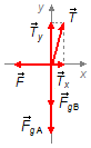
Direction x:
- \( {\vec T}_{x} \): component of the tension force in the x direction;
- \( \vec{F} \): external force applied to the bar.
\[
\begin{gather}
T_{x}-F=0\\[5pt]
T_{x}=F
\end{gather}
\]
using the result of item (b)
\[
\begin{gather}
T_{x}=3.75\;\text{N} \tag{XIV}
\end{gather}
\]
Direction y:
- \( {\vec T}_{y} \): component of the tension force in y direction;
- \( {\vec F}_{gA} \): gravitational force of segment AO;
- \( {\vec F}_{gB} \): gravitational force of segment BO.
\[
\begin{gather}
T_{y}-F_{gA}-F_{gB}=0\\[5pt]
T_{y}=F_{gA}+F_{gB}
\end{gather}
\]
substituting the problem data
\[
\begin{gather}
T_{y}=10+5 \\[5pt]
T_{y}=15\;N \tag{XV}
\end{gather}
\]
The tension force will be given by the Pythagorean Theorem (Figure 6)
\[
\begin{gather}
T^{2}=T_{x}^{2}+T_{y}^{2}
\end{gather}
\]
substituting expressions (XIV) and (XV)
\[
\begin{gather}
T^{2}=3.75^{2}+15^{2}\\[5pt]
T^{2}=14.1+225\\[5pt]
T^{2}=239.1\\[5pt]
T=\sqrt{239.1\;}
\end{gather}
\]
\[
\begin{gather}
\bbox[#FFCCCC,10px]
{T\simeq 15.4\;\text{N}}
\end{gather}
\]
advertisement

Fisicaexe - Physics Solved Problems by Elcio Brandani Mondadori is licensed under a Creative Commons Attribution-NonCommercial-ShareAlike 4.0 International License .